A miniature oscillator clip for the Duo 210 - revision 2
26 October 1994
Ronald Leenes
University of Twente
A brief history
A Duo-210 can be clock chipped. Some time ago I have posted a description of a small clip that can be piggybacked on top of the on-board crystal oscillator in a Duo-210. The clip is attached to an oscillator located in either the modem bay or RAM expansion bay of the Duo. I have successfully modified my own Duo using the described clip. My Duo 210 now runs at 32 MHz instead of the normal 25 MHz. The reason for constructing the clip is that I did not want to solder on the printed circuit board of the Duo. The original posting of the clip can be found on both Umich and Info-Mac archives as well as on Marc Schrier's Clock Chipping Home Page.
My girlfriend has acquired a Duo 210 as well. Obviously I could not keep my hands from that machine. Since I find the clip awkward to build myself (although it is a neat piece of engineering, if I may say so myself :-) ), I have thought of another solution. Here it is.
Warning
A warning is still in place. My Duo runs fine for some months now. The modification proves to be stable and safe. However, I must stress that modifying your Duo does void your warranty. Proceed at your own risk. I am not to blame in any way if you wreck your computer.
Shopping list
Construction
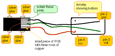
Take the small piece of printed circuit board. Solder three long isolated wires to the copper pads. The wires must be long enough to reach the replacement oscillator if the pcb is glued on top of the on-board oscillator (say 20 cm). Also solder the stripped wires you are going to glue to the pins of the on-board oscillator to the pcb (see the drawing for suggestions).
Cut of the pins of the replacement oscillator, leaving about 1 mm of pin free. Solder the isolated wires to the appropriate pins of the replacement oscillator. Wrap the some Scotch tape around the oscillator (to isolate it) and stick the oscillator to the bottom of the modem bay (or RAM expansion bay) using Scotch tape. Arrange the wires carefully over the Duo pcb.
Now glue the pcb on top of the on-board oscillator using ordinary glue. This will prevent the wires you are going to glue to the on-board oscillator from moving.
Bend the stripped wires to the pins of the on-board oscillator. They should touch the pins and stay in place, that's why I said you need stiff wire for this part.
On the joints apply several layers of silver glue. Since the silver glue can be applied with a pencil this is a fairly simple job. A steady hand will do the trick. Applying several layers (two or three) will take some time, since the glue has to dry thoroughly before the next layer can be applied. Consult the package of the glue for details (BTW You can use the Duo as soon as the silver glue is applied, there is no need to wait until it is dry).
Once the first layer of silver glue is applied carefully check your work and press the on button. Your Duo should start up normally.
The accompanying drawing gives an idea what it looks like when ready.
Please read the excellent file:
Mac Crystal Oscillator Speedup History 2.5 by Marc Schrier (schrier@mac.com) and my own DUO-210 speedup article before trying the mod described here.
Remember: proceed at your own risk. Although the modification does not require any soldering on the DUO's pcb itself and is removable (remove the glue using a small knife), it does void your warranty.
If you have any questions or remarks don't hesitate to contact me.
Ronald E. Leenes
University of Twente
Dept. of Public Administration and Public Policy
P.O. Box 217, 7500 AE Enschede, the Netherlands
r.e.leenes@bsk.utwente.nl